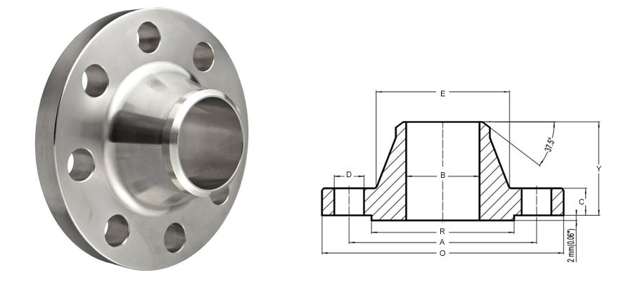
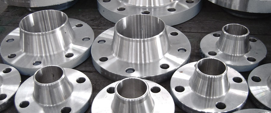
Welding Neck Flanges Manufacturer, Supplier and Exporter in Mumbai, India

We provide prompt delivery service for standard size of carbon steel weld neck flanges and stainless steel weld neck flanges. Weld neck pipe flanges are connected to the pipe by welding the pipe to the neck of the pipe flange, which helps to pass on the stress from the weld neck to the pipe itself.

Weld Neck Flange Specifications

Family Butt Weld Pipe Fitting Shape Coupling
Material Stainless Steel, Carbon Steel, Alloy Steel, Duplex Steel, Nickel Alloy Make TII
Size 1/2″-48″
Finish Shot Blast, Sand Blast, Electro polish End Bevelled
Marking TII-Specs-Description-Heat No. Packing Protected by Cap

Dimensions of Class 150 Weld Neck Flanges as per ASME B16.5

NPS F. Dia Dia of Bolt Circle Dia of Bolt Holes No. of Holes Thk of Flange Dia of Hub Length Dia of Bore Dia of R/F Depth of Socket
(MM) (Inches) O A D C E W/N
Y
W/N
B
R F
15 1/2 88.9 60.3 15.9 4 11.1 30.2 47.6 22.3 34.9 9.5
20 3/4 98.4 69.8 15.9 4 12.7 38.1 52.4 27.7 42.9 11.1
25 1 107.9 79.4 15.9 4 14.3 49.2 55.6 34.5 50.8 12.7
32 1 1/4 117.5 88.9 15.9 4 15.9 58.7 57.1 43.2 63.5 14.3
40 1 1/2 127.0 98.0 15.9 4 17.5 65.1 61.9 49.5 73.0 15.9
50 2 152.4 120.6 19.0 4 19.0 77.8 63.5 62.0 92.1 17.5
65 2 1/2 177.8 139.7 19.0 4 22.0 90.5 69.8 74.7 104.8 19.0
80 3 190.5 152.4 19.0 4 23.8 107.9 69.8 90.7 127.0 20.6
100 4 228.6 190.5 19.0 8 23.8 134.9 76.2 116.1 157.2 23.8
125 5 254.0 215.9 22.2 8 23.8 163.5 88.9 143.8 185.7 23.8
150 6 279.4 241.3 22.2 8 25.4 192.1 88.9 170.7 215.9 27.0
200 8 342.9 298.4 22.2 8 28.6 246.1 101.6 221.5 269.9 31.7
250 10 406.4 361.9 25.4 12 30.2 304.8 101.6 276.3 323.8 33.3
300 12 482.6 431.8 25.4 12 31.8 361.5 114.3 327.1 381.0 39.7
350 14 533.4 476.2 28.6 12 34.9 400.0 127.0 359.1 412.7 41.3
400 16 596.9 539.7 28.6 16 36.5 457.2 127.0 410.5 469.9 44.4
450 18 635.0 577.8 31.7 16 39.7 504.8 139.7 461.8 533.4 49.2
500 20 698.1 635.0 31.7 20 42.9 558.8 144.5 513.1 584.2 54.0
600 24 812.8 749.3 34.9 20 47.6 663.6 152.4 615 9 692.1 63.5

Dimensions of Class 300 Weld Neck Flanges as per ASME B16.5

NPS F. Dia Dia of Bolt Circle Dia of Bolt Holes No. of Holes Thk of Flange Dia of Hub Length Dia of Bore Dia of R/F Depth of Socket
(MM) (Inches) O A D C E W/N
Y
W/N
B
R F
15 1/2 95.2 66.7 15.9 4 14.3 38.1 52.4 22.3 34.9 9.5
20 3/4 117.5 82.5 19.0 4 15.9 47.6 57.1 27.7 42.9 11.1
25 1 123.8 88.9 19.0 4 17.5 54.0 61.9 34.5 50.8 12.7
32 1 1/4 133.3 98.4 19.0 4 19.0 63.5 65.1 43.2 63.5 14.3
40 1 1/2 155.6 114.3 22.2 4 20.6 69.8 68.3 49.5 73.0 15.9
50 2 165.1 127.0 19.0 8 22.2 84.1 69.8 62.0 92.1 17.5
65 2 1/2 190.5 149.2 22.2 8 25.4 100.0 76.2 74.7 104.8 19.0
80 3 209.5 168.3 22.2 8 28.6 117.5 79.4 90.7 127.0 20.6
100 4 254.0 200.0 22.2 8 31.8 146.0 85.7 116.1 157.2 23.8
125 5 279.4 234.9 22.2 8 34.9 177.8 98.4 143.8 185.7
150 6 317.5 269.9 22.2 12 36.5 206.4 98.4 170.7 215.9
200 8 381.0 330.2 25.4 12 41.3 260.3 111.1 221.5 269.9
250 10 444.5 387.3 28.6 16 47.6 320.7 117.5 276.3 323.8
300 12 520.7 450.8 31.7 16 50.8 374.6 130.2 327.1 381.0
350 14 584.2 514.3 31.7 20 54.0 425.4 142.9 359.1 412.7
400 16 647.7 571.5 34.9 20 57.2 482.6 146.0 410.5 469.9
450 18 711.2 628.5 34.9 24 60.3 533.4 158.7 461.8 533.4
500 20 774.7 685.8 34.9 24 63.5 587.4 161.9 513.1 584.2
600 24 914.4 812.8 41.3 24 69.8 701.7 168.3 615 9 692.1

Dimensions of Class 600 Weld Neck Flanges as per ASME B16.5

NPS F. Dia Dia of Bolt Circle Dia of Bolt Holes No. of Holes Thk of Flange Dia of Hub Length Dia of Bore Dia of R/F Depth of Socket
(MM) (Inches) O A D C E W/N
Y
W/N
B
R F
15 1/2 95.2 66.7 15.9 4 14.3 38.1 52.4 22.3 34.9 9.5
20 3/4 117.5 82.5 19.0 4 15.9 47.6 57.1 27.7 42.9 11.1
25 1 123.8 88.9 19.0 4 17.5 54.0 61.9 34.5 50.8 12.7
32 1 1/4 133.3 98.4 19.0 4 20.6 63.5 66.7 43.2 63.5 14.2
40 1 1/2 155.6 114.3 22.2 4 22.2 69.8 69.8 49.5 73.0 15.8
50 2 165.1 127.0 19.0 8 25.4 84.1 73.0 62.0 92.1 17.4
65 2 1/2 190.5 149.2 22.2 8 28.6 100.0 79.4 74.7 104.8 19.0
80 3 209.5 168.3 22.2 8 31.8 117.5 82.5 90.7 127.0
100 4 254.0 215.9 25.4 8 38.1 152.4 101.6 116.1 157.2
125 5 279.4 266.7 28.6 8 44.4 188.9 114.3 143.8 185.7
150 6 317.5 292.1 28.6 12 47.6 222.2 117.5 170.7 215.9
200 8 381.0 349.2 31.7 12 55.6 273.0 133.3 221.5 269.9
250 10 444.5 431.8 34.9 16 63.5 342.9 152.4 276.3 323.8
300 12 520.7 488.9 34.9 16 66.7 400.0 155.6 327.1 381.0
350 14 584.2 527.0 38.1 20 69.9 431.8 165.1 359.1 412.7
400 16 647.7 603.2 41.3 20 76.2 495.3 177.8 410.5 469.9
450 18 711.2 654.0 44.4 24 82.6 546.1 184.1 461.8 533.4
500 20 774.7 723.9 44.4 24 88.9 609.6 190.5 513.1 584.2
600 24 914.4 838.2 50.8 24 101.6 717.5 203.2 615 9 692.1

Dimensions of Class 900 Weld Neck Flanges as per ASME B16.5

NPS F. Dia Dia of Bolt Circle Dia of Bolt Holes No. of Holes Thk of Flange Dia of Hub Length Dia of Bore Dia of R/F Depth of Socket
(MM) (Inches) O A D C E W/N
Y
W/N
B
R F
15 1/2 120.6 82.5 22.2 4 22.2 38.1 60.3 22.3 34.9 9.5
20 3/4 130.2 88.9 22.2 4 25.4 44.4 69.8 27.7 42.9 11.1
25 1 149.2 101.6 25.4 4 28.6 52.4 73.0 34.5 50.8 12.7
32 1 1/4 158.7 111.1 25.4 4 28.6 63.5 73.0 43.2 63.5 14.2
40 1 1/2 177.8 123.8 28.6 4 31.8 69.8 82.5 49.5 73.0 15.8
50 2 215.9 165.1 25.4 8 38.1 104.8 101.6 62.0 92.1 17.4
65 2 1/2 244.5 190.5 28.6 8 41.3 123.8 104.8 74.7 104.8 19.0
80 3 241.3 190.5 25.4 8 38.1 127.0 101.6 90.7 127.0
100 4 292.1 234.9 31.7 8 44.4 158.7 114.3 116.0 157.1
125 5 349.2 279.4 35.0 8 50.8 190.5 127.0 143.7 185.7
150 6 381.0 317.5 31.7 12 55.6 234.9 139.7 170.6 215.9
200 8 469.9 393.7 38.1 12 63.5 298.4 162.0 221.4 269.3
250 10 546.1 469.9 38.1 16 69.8 368.3 184.1 276.3 323.8
300 12 609.6 533.4 38.1 20 79.3 419.1 200.0 327.1 381.0

Dimensions of Class 1500 Weld Neck Flanges as per ASME B16.5

NPS F. Dia Dia of Bolt Circle Dia of Bolt Holes No. of Holes Thk of Flange Dia of Hub Length Dia of Bore Dia of R/F Depth of Socket
(MM) (Inches) O A D C E W/N
Y
W/N
B
R F
15 1/2 120.6 82.5 22.2 4 22.2 38.1 60.3 22.3 34.9 9.5
20 3/4 130.2 88.9 22.2 4 25.4 44.4 69.8 27.7 42.9 11.1
25 1 149.2 101.6 25.4 4 28.6 52.4 73.0 34.5 50.8 12.7
32 1 1/4 158.7 111.1 25.4 4 28.6 63.5 73.0 43.2 63.5 14.2
40 1 1/2 177.8 123.8 28.6 4 31.8 69.8 82.5 49.5 73.0 15.8
50 2 215.9 165.1 25.4 8 38.1 104.8 101.6 62.0 92.1 17.4
65 2 1/2 244.5 190.5 28.6 8 41.3 123.8 104.8 74.7 104.8 19.0
80 3 266.7 203.2 31.7 8 47.6 133.3 117.5 90.7 127.0
100 4 311.1 241.3 34.9 8 54.0 161.9 123.0 116.0 157.1
125 5 374.6 292.1 41.3 8 73.0 196.8 155.6 143.7 185.7
150 6 393.7 317.5 38.1 12 82.6 228.6 171.4 170.6 215.9
200 8 482.6 393.5 44.4 12 92.1 292.1 212.7 221.4 269.3
250 10 584.2 482.6 50.8 12 107.9 368.3 254.0 276.3 323.8
300 12 673.1 571.5 54.0 16 123.8 450.8 282.5 327.1 381.0

Dimensions of Class 2500 Weld Neck Flanges as per ASME B16.5

NPS F. Dia Dia of Bolt Circle Dia of Bolt Holes No. of Holes Thk of Flange Dia of Hub Length Dia of Bore Dia of R/F Depth of Socket
(MM) (Inches) O A D C E W/N
Y
W/N
B
R F
15 1/2 133.7 88.9 22.2 4 30.2 42.9 73.0 22.3 34.9
20 3/4 139.7 95.2 22.2 4 31.7 50.8 79.4 27.7 42.9
25 1 158.7 107.9 25.4 4 34.9 57.1 88.9 34.5 50.8
32 1 1/4 184.1 130.2 28.6 4 38.1 73.0 95.2 43.2 63.5
40 1 1/2 203.2 146.0 31.7 4 44.4 79.4 111.1 49.5 73.0
50 2 234.9 171.9 28.6 8 50.8 95.2 127.0 62.4 92.1
65 2 1/2 266.7 196.8 31.7 8 57.1 114.3 142.9 74.7 104.8
80 3 304.8 228.6 34.9 8 66.7 133.3 168.3 90.7 127.0
100 4 355.6 273.0 41.3 8 76.2 165.1 190.5 116.1 157.2
125 5 419.1 323.8 47.6 8 92.1 203.2 228.6 143.8 185.7
150 6 482.6 368.3 54.0 8 107.9 234.9 273.0 170.7 215.9
200 8 552.4 438.1 54.0 12 127.0 304.8 317.5 221.5 269.9
250 10 673.1 539.7 66.7 12 165.1 374.6 419.1 276.3 323.8
300 12 762.0 619.1 73.0 12 184.1 441.3 463.5 327.1 381.0

Tolerance Chart

Welding Neck Tolerance
*Outside diameter O.D. 600 or smaller ± 1.6
O.D. over 600 ± 3.1
Inside diameter (bore) 250 and smaller ± 0.7
12 through 450 ± 1.6
500 and larger ± 3.1 − 1.6
diameter of contact face 1.6 raised face ± 0.7
6.3 raised face : tongue and grooved male and female ± 0.4
*diameter of hub at base when E is 600 or smaller ± 1.6
when E is over 600 ± 3.1
diameter of hub at pointing of welding 125 and smaller + 0.7 ± 0.7
150 and larger + 0.4 ± 0.0
thickness 450 and smaller + 3.1 − 0.0
500 and larger + 4.7 − 0.0
length through hub 250 and smaller ± 1.6
300 and larger ± 3.1
drilling bolt circle ± 1.6
bolt hale spacing ± 0.7
eccentricity with respect to bore 0.7 max