
Buttweld Fittings – Tolerances
Tolerance Chart
| All Fittings | 90° and 45° Elbows and Tees | Reducers and Lap. Joint Stub Ends | Caps | 180° Returns | Lap Joint Stub Ends | ||||||||
|---|---|---|---|---|---|---|---|---|---|---|---|---|---|
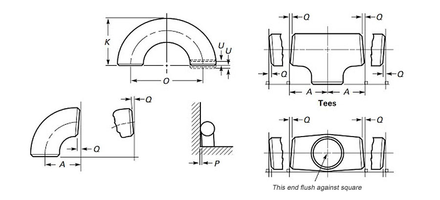
| NPS | Outside(1) Diameter at Bevel | Inside(2) Diameter at End | Wall(2) Thickness | C to E Dimension A, B, C, M. |
Over all Length F,H |
Over all Dimension E |
C to C Dimension O |
Back to Face Ends K |
Alignment of Ends U |
OD of Lap G |
Thickness of Lap T |
Fillet Radius of Lap R |
OD of Barrel |
| 1/2 to 2 1/2 | +1 | +0.8 | Not less than 87.5% of Nominal thickness | +2 | +2 | +4 | +7 | +7 | +1 | +0-1 | +2-0 | +0-1 | Refer Below Table |
| 3 to 3 1/2 | +1 | +1.6 | +2 | +2 | +4 | +7 | +7 | +1 | +0-1 | +2-0 | +0-1 | ||
| 4 | +2-1 | +1.6 | +2 | +2 | +4 | +7 | +7 | +1 | +0-1 | +2-0 | +0-2 | ||
| 5 to 6 | +3-1 | +1.6 | +2 | +2 | +7 | +7 | +7 | +1 | +0-1 | +2-0 | +0-2 | ||
| 8 | +2 | +1.6 | +2 | +2 | +7 | +7 | +7 | +1 | +0-1 | +2-0 | +0-2 | ||
| 10 | +4-3 | +3.2 | +2 | +2 | +7 | +10 | +7 | +2 | +0-2 | +2-0 | +0-2 | ||
| 12 to 18 | +4-3 | +3.2 | +3 | +3 | +7 | +10 | +7 | +2 | +0-2 | +2-0 | 0-2 | ||
| 20 to 24 | +6-5 | +4.8 | +3 | +3 | +7 | +10 | +7 | +2 | +0-2 | +2-0 | +0-2 | ||
| 26 to 30 | +7-5 | +4.8 | +3 | +3 | +10 | ||||||||
| 32 to 48 | +7-5 | +4.8 | +3 | +3 | +10 | ||||||||
| Outside Diameter of Barrel | |
|---|---|
| Max. | Min. |
| 0.896 | 0.809 |
| 1.106 | 1.019 |
| 1.376 | 1.284 |
| 1.716 | 1.629 |
| 1.966 | 1.869 |
| 2.456 | 2.344 |
| 2.966 | 2.844 |
| 3.596 | 3.469 |
| 4.096 | 3.969 |
| 4.593 | 4.469 |
| 5.683 | 5.532 |
| 6.743 | 6.594 |
| 8.743 | 8.594 |
| 10.913 | 10.719 |
| 12.913 | 12.719 |
| 14.170 | 13.969 |
| 16.180 | 15.969 |
| 18.190 | 17.969 |
| 20.240 | 19.969 |
| 22.240 | 21.969 |
| 24.240 | 23.969 |
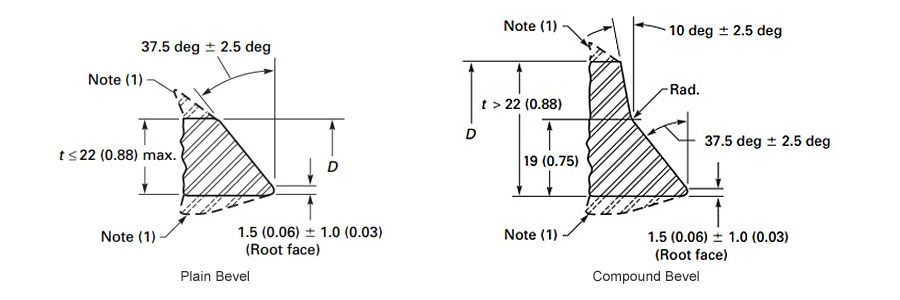
| Nominal Wall Thickness (f) | End Preparation |
|---|---|
| less than X | Cut square ur slightly chamber, at mtr’s option |
| X’ I0 0.88 incl. [22] | Plain bevel as in Sketch “a" above |
| more than 0.88 (22) | Compound bevel as in Sketch ”b”aboye |
| X* = 0.19 (5) Carbon steel cfierritic allay steal and 0.12(4) foraustenitic alloy steel. |
|
| Dimensions in parentheses are in millimeters. Others are in inches. |
|
| FIGURE 1 WELDING BEVELS AND ROOT FACE |
| Nominal Pipe | Angularity Tol. | |
|---|---|---|
| Off Angle | Off Plane | |
| Size | Q | P |
| 1/ 2 to 4 | +1 | +2 |
| 5 to 8 | +2 | +4 |
| 10 to 12 | +8 | +5 |
| 14 to 16 | +8 | +7 |
| 18 to 24 | +4 | +10 |
| 26 to 30 | +5 | +10 |
| 32 to 42 | +5 | +13 |
| 44 to 48 | +5 | +20 |