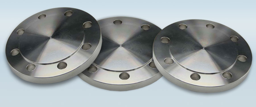
Blind Flanges
Blind Flange Specifications
| Family | Blind Flange | Shape | Blind |
|---|---|---|---|
| Material | Stainless Steel, Carbon Steel, Alloy Steel, Duplex Steel, Nickel Alloy | Make | TII |
| Size | 1/2″-48″ | ||
| Finish | Shot Blast, Sand Blast, Electro polish | End | Bevelled |
| Marking | TII-Specs-Description-Heat No. | Packing | Protected by Cap |
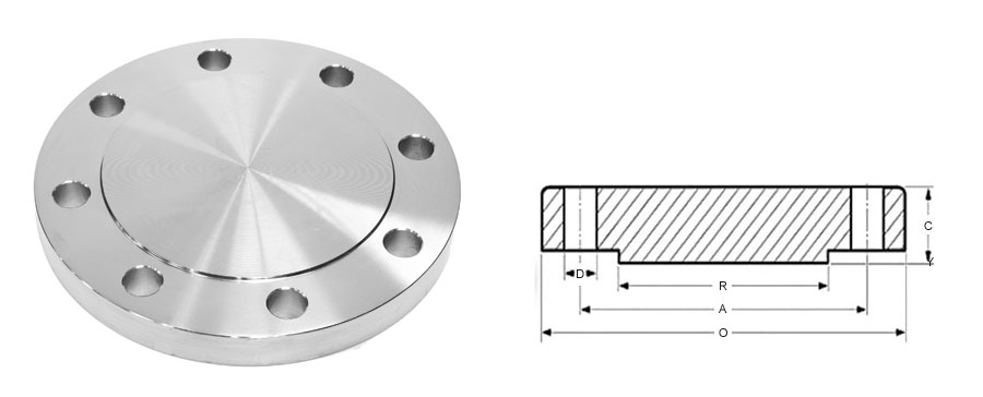
Dimensions of Class 150 Blind Flanges as per ASME B16.5
| NPS | F. Dia | Dia of Bolt Circle | Dia of Bolt Holes | No. of Holes | Thk of Flange | Dia of Hub | Dia of R/F | |
|---|---|---|---|---|---|---|---|---|
| (MM) | (Inches) | O | A | D | C | E | R | |
| 15 | 1/2 | 88.9 | 60.3 | 15.9 | 4 | 11.1 | 30.2 | 34.9 |
| 20 | 3/4 | 98.4 | 69.8 | 15.9 | 4 | 12.7 | 38.1 | 42.9 |
| 25 | 1 | 107.9 | 79.4 | 15.9 | 4 | 14.3 | 49.2 | 50.8 |
| 32 | 1 1/4 | 117.5 | 88.9 | 15.9 | 4 | 15.9 | 58.7 | 63.5 |
| 40 | 1 1/2 | 127.0 | 98.0 | 15.9 | 4 | 17.5 | 65.1 | 73.0 |
| 50 | 2 | 152.4 | 120.6 | 19.0 | 4 | 19.0 | 77.8 | 92.1 |
| 65 | 2 1/2 | 177.8 | 139.7 | 19.0 | 4 | 22.0 | 90.5 | 104.8 |
| 80 | 3 | 190.5 | 152.4 | 19.0 | 4 | 23.8 | 107.9 | 127.0 |
| 100 | 4 | 228.6 | 190.5 | 19.0 | 8 | 23.8 | 134.9 | 157.2 |
| 125 | 5 | 254.0 | 215.9 | 22.2 | 8 | 23.8 | 163.5 | 185.7 |
| 150 | 6 | 279.4 | 241.3 | 22.2 | 8 | 25.4 | 192.1 | 215.9 |
| 200 | 8 | 342.9 | 298.4 | 22.2 | 8 | 28.6 | 246.1 | 269.9 |
| 250 | 10 | 406.4 | 361.9 | 25.4 | 12 | 30.2 | 304.8 | 323.8 |
| 300 | 12 | 482.6 | 431.8 | 25.4 | 12 | 31.8 | 361.5 | 381.0 |
| 350 | 14 | 533.4 | 476.2 | 28.6 | 12 | 34.9 | 400.0 | 412.7 |
| 400 | 16 | 596.9 | 539.7 | 28.6 | 16 | 36.5 | 457.2 | 469.9 |
| 450 | 18 | 635.0 | 577.8 | 31.7 | 16 | 39.7 | 504.8 | 533.4 |
| 500 | 20 | 698.1 | 635.0 | 31.7 | 20 | 42.9 | 558.8 | 584.2 |
| 600 | 24 | 812.8 | 749.3 | 34.9 | 20 | 47.6 | 663.6 | 692.1 |
Dimensions of Class 300 Blind Flanges as per ASME B16.5
| NPS | F. Dia | Dia of Bolt Circle | Dia of Bolt Holes | No. of Holes | Thk of Flange | Dia of Hub | Dia of R/F | |
|---|---|---|---|---|---|---|---|---|
| (MM) | (Inches) | O | A | D | C | E | R | |
| 15 | 1/2 | 95.2 | 66.7 | 15.9 | 4 | 14.3 | 38.1 | 34.9 |
| 20 | 3/4 | 117.5 | 82.5 | 19.0 | 4 | 15.9 | 47.6 | 42.9 |
| 25 | 1 | 123.8 | 88.9 | 19.0 | 4 | 17.5 | 54.0 | 50.8 |
| 32 | 1 1/4 | 133.3 | 98.4 | 19.0 | 4 | 19.0 | 63.5 | 63.5 |
| 40 | 1 1/2 | 155.6 | 114.3 | 22.2 | 4 | 20.6 | 69.8 | 73.0 |
| 50 | 2 | 165.1 | 127.0 | 19.0 | 8 | 22.2 | 84.1 | 92.1 |
| 65 | 2 1/2 | 190.5 | 149.2 | 22.2 | 8 | 25.4 | 100.0 | 104.8 |
| 80 | 3 | 209.5 | 168.3 | 22.2 | 8 | 28.6 | 117.5 | 127.0 |
| 100 | 4 | 254.0 | 200.0 | 22.2 | 8 | 31.8 | 146.0 | 157.2 |
| 125 | 5 | 279.4 | 234.9 | 22.2 | 8 | 34.9 | 177.8 | 185.7 |
| 150 | 6 | 317.5 | 269.9 | 22.2 | 12 | 36.5 | 206.4 | 215.9 |
| 200 | 8 | 381.0 | 330.2 | 25.4 | 12 | 41.3 | 260.3 | 269.9 |
| 250 | 10 | 444.5 | 387.3 | 28.6 | 16 | 47.6 | 320.7 | 323.8 |
| 300 | 12 | 520.7 | 450.8 | 31.7 | 16 | 50.8 | 374.6 | 381.0 |
| 350 | 14 | 584.2 | 514.3 | 31.7 | 20 | 54.0 | 425.4 | 412.7 |
| 400 | 16 | 647.7 | 571.5 | 34.9 | 20 | 57.2 | 482.6 | 469.9 |
| 450 | 18 | 711.2 | 628.5 | 34.9 | 24 | 60.3 | 533.4 | 533.4 |
| 500 | 20 | 774.7 | 685.8 | 34.9 | 24 | 63.5 | 587.4 | 584.2 |
| 600 | 24 | 914.4 | 812.8 | 41.3 | 24 | 69.8 | 701.7 | 692.1 |
Dimensions of Class 600 Blind Flanges as per ASME B16.5
| NPS | F. Dia | Dia of Bolt Circle | Dia of Bolt Holes | No. of Holes | Thk of Flange | Dia of Hub | Dia of R/F | |
|---|---|---|---|---|---|---|---|---|
| (MM) | (Inches) | O | A | D | C | E | R | |
| 15 | 1/2 | 95.2 | 66.7 | 15.9 | 4 | 14.3 | 38.1 | 34.9 |
| 20 | 3/4 | 117.5 | 82.5 | 19.0 | 4 | 15.9 | 47.6 | 42.9 |
| 25 | 1 | 123.8 | 88.9 | 19.0 | 4 | 17.5 | 54.0 | 50.8 |
| 32 | 1 1/4 | 133.3 | 98.4 | 19.0 | 4 | 20.6 | 63.5 | 63.5 |
| 40 | 1 1/2 | 155.6 | 114.3 | 22.2 | 4 | 22.2 | 69.8 | 73.0 |
| 50 | 2 | 165.1 | 127.0 | 19.0 | 8 | 25.4 | 84.1 | 92.1 |
| 65 | 2 1/2 | 190.5 | 149.2 | 22.2 | 8 | 28.6 | 100.0 | 104.8 |
| 80 | 3 | 209.5 | 168.3 | 22.2 | 8 | 31.8 | 117.5 | 127.0 |
| 100 | 4 | 254.0 | 215.9 | 25.4 | 8 | 38.1 | 152.4 | 157.2 |
| 125 | 5 | 279.4 | 266.7 | 28.6 | 8 | 44.4 | 188.9 | 185.7 |
| 150 | 6 | 317.5 | 292.1 | 28.6 | 12 | 47.6 | 222.2 | 215.9 |
| 200 | 8 | 381.0 | 349.2 | 31.7 | 12 | 55.6 | 273.0 | 269.9 |
| 250 | 10 | 444.5 | 431.8 | 34.9 | 16 | 63.5 | 342.9 | 323.8 |
| 300 | 12 | 520.7 | 488.9 | 34.9 | 16 | 66.7 | 400.0 | 381.0 |
| 350 | 14 | 584.2 | 527.0 | 38.1 | 20 | 69.9 | 431.8 | 412.7 |
| 400 | 16 | 647.7 | 603.2 | 41.3 | 20 | 76.2 | 495.3 | 469.9 |
| 450 | 18 | 711.2 | 654.0 | 44.4 | 24 | 82.6 | 546.1 | 533.4 |
| 500 | 20 | 774.7 | 723.9 | 44.4 | 24 | 88.9 | 609.6 | 584.2 |
| 600 | 24 | 914.4 | 838.2 | 50.8 | 24 | 101.6 | 717.5 | 692.1 |
Dimensions of Class 900 Blind Flanges as per ASME B16.5
| NPS | F. Dia | Dia of Bolt Circle | Dia of Bolt Holes | No. of Holes | Thk of Flange | Dia of Hub | Dia of R/F | |
|---|---|---|---|---|---|---|---|---|
| (MM) | (Inches) | O | A | D | C | E | R | |
| 15 | 1/2 | 120.6 | 82.5 | 22.2 | 4 | 22.2 | 38.1 | 34.9 |
| 20 | 3/4 | 130.2 | 88.9 | 22.2 | 4 | 25.4 | 44.4 | 42.9 |
| 25 | 1 | 149.2 | 101.6 | 25.4 | 4 | 28.6 | 52.4 | 50.8 |
| 32 | 1 1/4 | 158.7 | 111.1 | 25.4 | 4 | 28.6 | 63.5 | 63.5 |
| 40 | 1 1/2 | 177.8 | 123.8 | 28.6 | 4 | 31.8 | 69.8 | 73.0 |
| 50 | 2 | 215.9 | 165.1 | 25.4 | 8 | 38.1 | 104.8 | 92.1 |
| 65 | 2 1/2 | 244.5 | 190.5 | 28.6 | 8 | 41.3 | 123.8 | 104.8 |
| 80 | 3 | 241.3 | 190.5 | 25.4 | 8 | 38.1 | 127.0 | 127.0 |
| 100 | 4 | 292.1 | 234.9 | 31.7 | 8 | 44.4 | 158.7 | 157.1 |
| 125 | 5 | 349.2 | 279.4 | 35.0 | 8 | 50.8 | 190.5 | 185.7 |
| 150 | 6 | 381.0 | 317.5 | 31.7 | 12 | 55.6 | 234.9 | 215.9 |
| 200 | 8 | 469.9 | 393.7 | 38.1 | 12 | 63.5 | 298.4 | 269.3 |
| 250 | 10 | 546.1 | 469.9 | 38.1 | 16 | 69.8 | 368.3 | 323.8 |
| 300 | 12 | 609.6 | 533.4 | 38.1 | 20 | 79.3 | 419.1 | 381.0 |
Dimensions of Class 1500 Blind Flanges as per ASME B16.5
| NPS | F. Dia | Dia of Bolt Circle | Dia of Bolt Holes | No. of Holes | Thk of Flange | Dia of Hub | Dia of R/F | |
|---|---|---|---|---|---|---|---|---|
| (MM) | (Inches) | O | A | D | C | E | R | |
| 15 | 1/2 | 120.6 | 82.5 | 22.2 | 4 | 22.2 | 38.1 | 34.9 |
| 20 | 3/4 | 130.2 | 88.9 | 22.2 | 4 | 25.4 | 44.4 | 42.9 |
| 25 | 1 | 149.2 | 101.6 | 25.4 | 4 | 28.6 | 52.4 | 50.8 |
| 32 | 1 1/4 | 158.7 | 111.1 | 25.4 | 4 | 28.6 | 63.5 | 63.5 |
| 40 | 1 1/2 | 177.8 | 123.8 | 28.6 | 4 | 31.8 | 69.8 | 73.0 |
| 50 | 2 | 215.9 | 165.1 | 25.4 | 8 | 38.1 | 104.8 | 92.1 |
| 65 | 2 1/2 | 244.5 | 190.5 | 28.6 | 8 | 41.3 | 123.8 | 104.8 |
| 80 | 3 | 266.7 | 203.2 | 31.7 | 8 | 47.6 | 133.3 | 127.0 |
| 100 | 4 | 311.1 | 241.3 | 34.9 | 8 | 54.0 | 161.9 | 157.1 |
| 125 | 5 | 374.6 | 292.1 | 41.3 | 8 | 73.0 | 196.8 | 185.7 |
| 150 | 6 | 393.7 | 317.5 | 38.1 | 12 | 82.6 | 228.6 | 215.9 |
| 200 | 8 | 482.6 | 393.5 | 44.4 | 12 | 92.1 | 292.1 | 269.3 |
| 250 | 10 | 584.2 | 482.6 | 50.8 | 12 | 107.9 | 368.3 | 323.8 |
| 300 | 12 | 673.1 | 571.5 | 54.0 | 16 | 123.8 | 450.8 | 381.0 |
Dimensions of Class 2500 Blind Flanges as per ASME B16.5
| NPS | F. Dia | Dia of Bolt Circle | Dia of Bolt Holes | No. of Holes | Thk of Flange | Dia of Hub | Dia of R/F | |
|---|---|---|---|---|---|---|---|---|
| (MM) | (Inches) | O | A | D | C | E | R | |
| 15 | 1/2 | 133.7 | 88.9 | 22.2 | 4 | 30.2 | 42.9 | 34.9 |
| 20 | 3/4 | 139.7 | 95.2 | 22.2 | 4 | 31.7 | 50.8 | 42.9 |
| 25 | 1 | 158.7 | 107.9 | 25.4 | 4 | 34.9 | 57.1 | 50.8 |
| 32 | 1 1/4 | 184.1 | 130.2 | 28.6 | 4 | 38.1 | 73.0 | 63.5 |
| 40 | 1 1/2 | 203.2 | 146.0 | 31.7 | 4 | 44.4 | 79.4 | 73.0 |
| 50 | 2 | 234.9 | 171.9 | 28.6 | 8 | 50.8 | 95.2 | 92.1 |
| 65 | 2 1/2 | 266.7 | 196.8 | 31.7 | 8 | 57.1 | 114.3 | 104.8 |
| 80 | 3 | 304.8 | 228.6 | 34.9 | 8 | 66.7 | 133.3 | 127.0 |
| 100 | 4 | 355.6 | 273.0 | 41.3 | 8 | 76.2 | 165.1 | 157.2 |
| 125 | 5 | 419.1 | 323.8 | 47.6 | 8 | 92.1 | 203.2 | 185.7 |
| 150 | 6 | 482.6 | 368.3 | 54.0 | 8 | 107.9 | 234.9 | 215.9 |
| 200 | 8 | 552.4 | 438.1 | 54.0 | 12 | 127.0 | 304.8 | 269.9 |
| 250 | 10 | 673.1 | 539.7 | 66.7 | 12 | 165.1 | 374.6 | 323.8 |
| 300 | 12 | 762.0 | 619.1 | 73.0 | 12 | 184.1 | 441.3 | 381.0 |
Tolerance Chart
| Blind Flanges Tolerance | |||
|---|---|---|---|
| *Outside diameter | O.D. 500 or smaller | ± 1.6 | |
| O.D. over 600 | ± 3.1 | ||
| Inside diameter | threaded | to standard gauge limits slip on: lap joint: socket welding | |
| 250 and smaller | + 0.7 | − 0.0 | |
| 300 and largee | + 1.6 | − 0.0 | |
| diameter of counter bore | threaded | ||
| 250 and smaller | + 0.7 | − 0.0 | |
| 300 and large | + 1.6 | − 0.0 | |
| *Outside diameter of hub | 300 and smaller | + 2.3 | − 1.6 |
| 350 and larger | ± 3.1 | ||
| diameter of contract face | 1.6 raised face | ± 0.7 | |
| 6.3 raised face : tongue and grooved male and female | ± 0.4 | ||
| thickness | 450 and smaller | + 3.1 | − 0.0 |
| 500 and larger | + 4.7 | − 0.0 | |
| *length through hub | 250 and smaller | ± 1.6 | |
| 300 and larger | ± 3.1 | ||
| drilling | bolt circle | ± 1.6 | |
| bolt hole spacing | ± 0.7 | ||
| eccenticity with respect of to bore | 0.7 max | ||